
7. Voice Parameter Reference
This chapter explains what each control changes, when it applies, and any important conditions.
7.1 Operator Basics
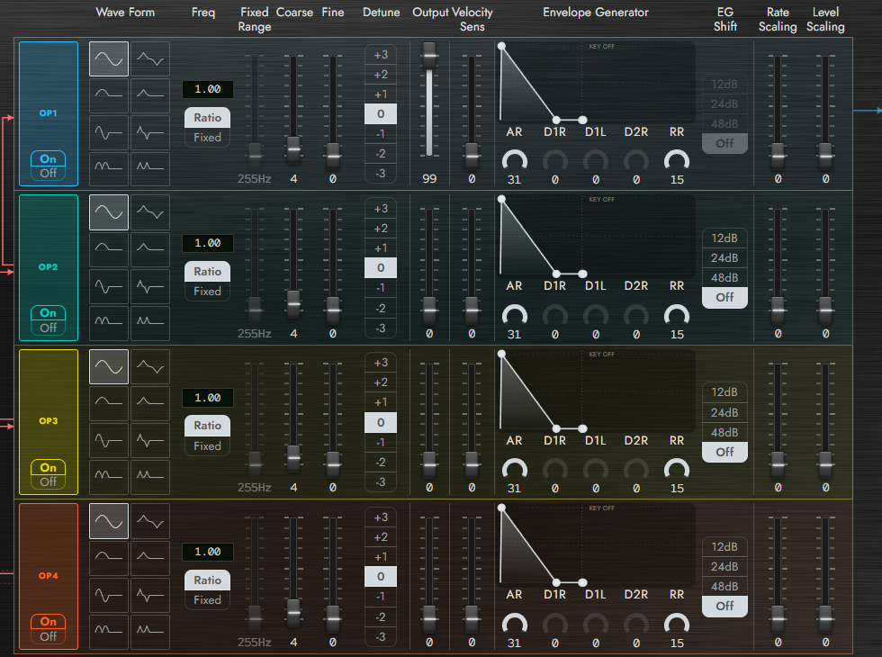
Each row represents one operator. From left to right, the controls cover waveform, frequency, Output, EG, and Scaling. Use this overview to locate the controls shown in the detailed images below.
On / Off and Wave Form
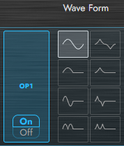
On / Off enables or silences an operator. Disabling a modulator removes its modulation; disabling a carrier removes its audio contribution. Voice files retain this state, but the hardware's standard Voice bulk data does not contain operator On / Off.
You can also toggle an operator by right-clicking anywhere within its area, including over knobs and the EG graph. Right-click again to restore its previous state. This is useful for comparing each operator's contribution to the sound.
Wave Form selects W1–W8. W1 is a sine wave; the other shapes are derived from a sine and contain harmonics. The same waveform has different effects in a carrier and a modulator.
Ratio / Fixed, Coarse, and Fine
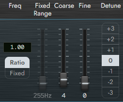
| Control | Range / choices | Function |
|---|---|---|
| Freq | Ratio / Fixed | Frequency relative to the key, or absolute Hz |
| Coarse | 0–63 | Coarse adjustment; Ratio uses a 64-entry table |
| Fine | 0–15 | Fine adjustment above Coarse |
| Fixed Range | 255 Hz / 510 Hz / 1 / 2 / 4 / 8 / 16 / 32 kHz | Frequency band in Fixed mode |
| Detune | -3 to +3 | Small pitch offset; 0 is centered |
Ratio Coarse selects ratios from 0.50 to 25.95. Coarse 4 is ratio 1.00. Do not read the step number as the ratio. Freq shows the resulting value including Fine.
Fixed uses an absolute frequency rather than following keyboard pitch. Higher ranges cover more frequency at coarser resolution. The highest band includes aliasing, as on the hardware.
Output and Velocity Sens
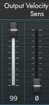
Output (0–99) sets operator level. It mainly controls loudness on a carrier and modulation depth on a modulator. The relationship between the number and level is not linear.
Velocity Sens (0–7) sets sensitivity to playing strength. At 0, velocity does not change operator level. Higher values reduce its output more on soft notes. On a modulator, this makes timbre respond to velocity.
7.2 Envelope Generator
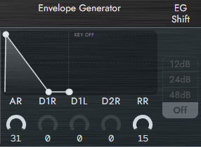
The envelope controls operator level from note-on to release. Graph handles correspond to the controls. Read the graph as a relationship between stages, not as a fixed time scale in seconds.
| Label | Range | Function / condition |
|---|---|---|
| AR (Attack Rate) | 0–31 | Attack speed; larger is faster. At 0 the envelope does not rise |
| D1R (Decay 1 Rate) | 0–31 | Decay toward D1L; 0 holds this stage |
| D1L (Decay 1 Level) | 0–15 | First decay's destination; 15 is maximum, 0 minimum |
| D2R (Decay 2 Rate) | 0–31 | Further decay while held; 0 sustains D1L |
| RR (Release Rate) | 1–15 | Release speed; 1 slowest, 15 fastest |
| EG Shift | Off / 48dB / 24dB / 12dB | Raises the envelope floor; OP1 is fixed Off |
Higher rates make the envelope faster and the sound shorter. RR has no zero setting. With D1R at 0, the envelope does not progress toward D1L, so changes to D1L or D2R may not produce the expected result.
EG Shift limits attenuation below the peak. A modulator can keep contributing after its decay. For an ordinary release tail, check RR and Reverb Rate first.
7.3 Keyboard Scaling
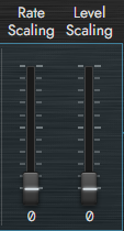
Rate Scaling (0–3) speeds up the envelope on higher keys. It affects decay and release as well as attack. Zero means no scaling.
Level Scaling (0–99) reduces operator output toward the upper keyboard. It changes level on a carrier and modulation on a modulator. Adjust the modulator if the upper range becomes too harsh.
7.4 Algorithm and Feedback
Algorithm (1–8) selects the connections. Algorithm 1 is serial; Algorithm 8 has four independent carriers. Follow the diagram's lines to identify which operators reach the output.
Feedback (0–7) sets OP4's self-modulation. Zero disables feedback. Higher values make the waveform more complex and can produce rough textures. Changing Algorithm also changes the route from OP4 to the output.
7.5 LFO
Shape, Speed, and Onset
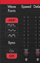
| Label | Range / choices | Function |
|---|---|---|
| Wave Form | Saw Up / Square / Triangle / S/Hold | Modulation shape; S/Hold changes between held random values |
| Speed | 0–99 | Larger values run faster |
| Delay | 0–99 | Delayed onset of modulation after a note |
| Sync | On / Off | Restarts LFO phase with note-on |
Pitch and Amplitude Modulation
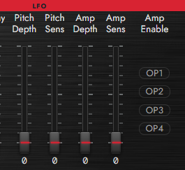
| Label | Range / choices | Function |
|---|---|---|
| Pitch Depth | 0–99 | Pitch modulation depth |
| Pitch Sens | 0–7 | Sensitivity to pitch modulation |
| Amp Depth | 0–99 | Amplitude modulation depth |
| Amp Sens | 0–3 | Sensitivity to amplitude modulation |
| Amp Enable | On / Off per OP | Operators receiving amplitude modulation |
Pitch Depth has no effect with Pitch Sens at 0. Amplitude modulation needs Amp Depth, Amp Sens, and the corresponding OP's Amp Enable. Modulating only a modulator changes timbre as well as the resulting level.
Caution
This LFO's Sync means keyboard synchronization. It is not the Effects rack's BPM synchronization and does not select DAW note values.
In Performance, each part can choose Own, shared LFOs, or Vib. See Chapter 8.
7.6 Mod Wheel
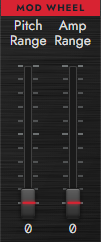
MOD WHEEL Pitch Range / Amp Range (0–99 each) set modulation from CC1. Also check LFO sensitivities and operator Amp Enable.
7.7 Mono / Poly / Portamento
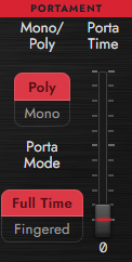
Mono / Poly selects monophonic or polyphonic playing. Mono uses last-note priority. Poly is limited by Settings Polyphony and, in Performance, the part's Voices allocation.
Porta Time (0–99) sets pitch transition duration; 0 is immediate. Porta Mode selects the trigger condition.
| Mode | Behavior |
|---|---|
| Full Time | Glide when the portamento switch is On and Time is above 0 |
| Fingered | Glide on overlapping notes in Mono. Set Time to 0 to stop it |
Fingered applies in Mono. Poly uses Full Time. Distinguish MIDI CC65 from the hardware Foot SW assignment in Hardware Params.
7.8 Function
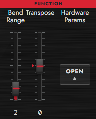
Bend Range (0–12) sets pitch-bend range in semitones. Zero disables pitch change. Transpose (-24 to +24) transposes the Voice in semitones; Performance part Shift is separate.
7.9 Hardware Params
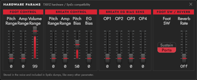
Open Hardware Params → OPEN to edit the following. These advanced settings provide TX81Z compatibility and also affect Synth81Z without connected hardware.
| Item | Range / choices | Function / condition |
|---|---|---|
| Foot Control Pitch Range / Amp Range | 0–99 each | Pitch / amplitude modulation from CC4 |
| Foot Control Volume Range | 0–99 | Foot-controller level range |
| Breath Control Pitch Range / Amp Range | 0–99 each | Modulation from CC2 or channel aftertouch |
| Breath Control Pitch Bias | 0–99; center 50 | Direct pitch offset independent of LFO; 50 is neutral |
| Breath Control EG Bias | 0–99 | Breath-controlled envelope level amount |
| Breath EG Bias Sens (OP1–4) | 0–7 each | Each operator's sensitivity to EG Bias |
| Foot SW | Sustain / Porta | Exclusive hardware foot-switch assignment |
| Reverb Rate | 0–7 | Shapes the low-level envelope tail; 0 is Off |
Breath EG Bias sets the amount, and each OP's Sens sets its response. A zero setting on either side disables that path. Channel aftertouch uses the breath-control path.
Note
Voice Reverb Rate changes envelope decay. It is distinct from the spatial Reverb in the Effects rack.