
8. Patch / Performance Reference
This chapter describes the parameters that relate to how you perform and how you layer tones, rather than the sound itself. On screen, these correspond to the light-blue sections (Patch scope). For where each section is located on screen, see → Chapter 4 "Screen Tour"; for the sound-side (white section) parameters, see → Chapter 7 "Tone Parameter Reference".
Note
The unit of storage in Synth-80 is the Patch (extension .80p). A single Patch contains two tones, the Upper Tone and the Lower Tone, plus the performance settings described in this chapter, the Effect Chain, and the Patch Volume. For the overall picture of Patch / Tone, see → Chapter 5 "Understanding Preset / Patch / Tone".
8.1 What Are Patch-Scope Parameters?
Whereas the white sections (Tone) determine "the sound of each of the Upper / Lower tones," the light-blue sections (Patch scope) determine "how those two tones are layered and how they are played." Think of them as a framework one level above the sound itself, covering everything from when a MIDI note is received to when sound is produced.
Patch-scope parameters fall into two kinds, depending on their range of effect.
| Kind | Main items included | How Upper / Lower are handled |
|---|---|---|
| Global | Key Mode, Split Point, Balance, Master Tune, Master Dynamics Sens, Stereo Mode, Patch Volume | A single value shared by Upper / Lower |
| per-section (per layer) | Octave Shift, Assign Mode, Unison Detune, Hold, Glide, Pitch Bend Sens / Bend Mode, AT Sens, LFO-2 Rate / Sync / Destination | Can hold separate values for Upper / Lower |
The per-section parameters hold independent values for Upper and Lower even on the actual MKS-80 (internally, they are distinguished by the Group byte of the IPR as Upper = 01 / Lower = 02). Synth-80 follows this behavior, letting you set these performance and expression values separately for Upper and Lower.
Note
In WHOLE mode, the per-section values for Upper / Lower are synchronized bidirectionally, and when you switch the edit target, the Upper value is copied to Lower. In SPLIT / DUAL, the two are treated independently.
The per-section parameters are also shown in light blue on screen. When you want to set them while comparing Upper / Lower side by side, switch the Tone editor to expanded view, where you can check the values of both layers in two rows, upper and lower (→ Chapter 4 "Screen Tour" §4.6).

8.2 MASTER (Master Tune / Dynamics Sens / Stereo Mode)
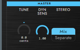
The MASTER section gathers three global settings that affect the whole Patch.
Master Tune
Fine-tunes the pitch of all VCOs within a range of ±50 cents. This is an overall correction for matching the tuning to the actual hardware or to other instruments.
Master Dynamics Sens
Adjusts the depth of the response curve to MIDI Velocity (1–127) across the whole Patch at once. Lower values reduce the difference between soft and hard playing, while higher values widen the dynamic range. It works multiplicatively with the DYNAMICS TIME / DYNAMICS LEVEL of each envelope on the Tone side (for DYNAMICS TIME / LEVEL themselves, see → Chapter 7 "Tone Parameter Reference").
Stereo Mode
Determines how Upper / Lower are routed to the stereo bus. This reproduces the output assignment on the rear panel of the actual MKS-80.
| Option | Meaning |
|---|---|
| Mix | Mixes Upper / Lower into mono via BALANCE and sends the same signal to both L / R. |
| Separate | Outputs L = Upper, R = Lower separately. BALANCE has no effect (this corresponds to wiring that bundles the Upper / Lower outputs of the rear-panel XLR connectors as a stereo pair). |
8.3 KEY MODE (Key Mode / Split Point)
Key Mode
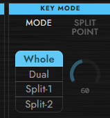
This is the core setting of the Patch, determining how the two tones, Upper and Lower, are combined.
| Option | Meaning | Voice allocation |
|---|---|---|
| WHOLE | Plays the entire keyboard with the Upper Tone only. Lower is disabled. | Up to 8 voices (extended by the Polyphony setting) |
| DUAL | Both Upper and Lower sound at the same time on the same key (layer). BALANCE sets the volume ratio. | 4 voices each for Upper / Lower |
| SPLIT 1 | Splits the keyboard at the Split Point, playing the low side = Lower and the high side = Upper. The MIDI channel is shared. | 4 voices each for Upper / Lower |
| SPLIT 2 | Splits by MIDI channel. Base channel = Upper, base channel + 1 = Lower. | 4 voices each for Upper / Lower |
In DUAL and SPLIT, the voice pool is divided between Upper and Lower. When the maximum polyphony (Polyphony) is 8, Upper and Lower each use up to 4 voices. If layered sounds or chords cut off earlier than expected, raising the Polyphony may help (→ Chapter 12 "Settings and Performance").
Split Point
When Key Mode is SPLIT 1, this specifies the MIDI note at which the keyboard is split. This key and above are assigned to Upper, and below it to Lower. It has no effect in WHOLE / DUAL / SPLIT 2 (in these modes, the Split Point display is dimmed).
8.4 BALANCE (Upper / Lower Volume Balance)
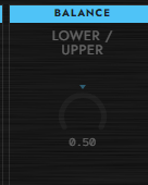
This is a global setting that determines the volume ratio between the Upper Tone and the Lower Tone. Balance affects the sound only when Key Mode is DUAL or one of the SPLIT modes. In WHOLE mode, Lower is always silent, so moving this knob does not change the result. Balance also has no effect when Stereo Mode is set to Separate (see §8.2).
8.5 OCT SHIFT (Octave Shift)
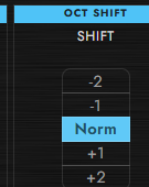
Transposes all received MIDI notes in octave steps. Use it when you want to shift the pitch of an entire layer at once, separately from the VCO range (Foot setting).
Octave Shift is a per-section parameter. In DUAL / SPLIT, Upper and Lower can hold separate values, so you can, for example, layer the Lower one octave lower.
8.6 ASSIGN MODE (Assign Mode / Unison Detune / Hold)
The ASSIGN MODE section determines how received notes are assigned to voices, and whether notes are held. All of these are per-section parameters.
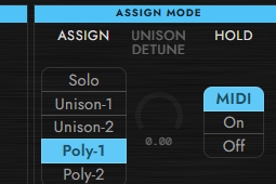
Assign Mode
| Option | Meaning |
|---|---|
| SOLO | Monophonic. The most recently pressed key always takes priority, and only one voice sounds. |
| UNISON-1 | Stacks all voices onto a single note (mono, last-note priority). The amount of pitch offset between the stacked voices is set by Unison Detune. |
| UNISON-2 | Dynamically redistributes the number of voices according to the number of keys held. 1 key = all voices, 2 keys = 1/2 each, 3–4 keys = 1/4 each, 5 or more keys = 1 voice each. |
| POLY-1 | Polyphonic. Assigns one voice per key. |
| POLY-2 | With 2 keys or fewer, stacks 4 voices each; with 3 or more keys, it automatically switches to 1 key = 1 voice. |
Note
The number of voices stacked in UNISON-1 / UNISON-2 follows the Polyphony setting. Setting Polyphony to 24 stacks up to 24 voices on a single note for a thicker unison (→ Chapter 12 "Settings and Performance").
Note
POLY-1 is one voice per key. When you repeat the same note, the previous voice is reused. Note that VCF Key Follow (cutoff tracking based on the key) also follows Glide (portamento). Pitch Bend does not affect the VCF, so bending the pitch does not move the filter cutoff—an asymmetric behavior (Pitch Bend acts only on VCO pitch).
Unison Detune
The amount of pitch offset between the voices stacked in UNISON-1 / UNISON-2 / POLY-2. At 0 they are perfectly in phase; raising it detunes the voices from one another, adding thickness. It has no effect in SOLO / POLY-1, since there are no voices to stack.
Hold
Determines whether sound continues to be held after note-off.
| Option | Meaning |
|---|---|
| MIDI | Holds notes while the MIDI Damper (CC #64, sustain pedal) is ON. |
| ON | Always holds. Even when you release the keys, the envelope does not enter Release. |
| OFF | Hold disabled. The MIDI Damper is also ignored. |
8.7 GLIDE (Glide / Portamento)
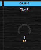
Sets the time over which the pitch transitions smoothly from the previous note to a new note (portamento). In the Poly modes, each voice glides independently. Glide is a per-section parameter.
VCF Key Follow follows Glide. When the pitch moves smoothly during a glide, and Key Follow is active, the filter cutoff transitions slowly along with it.
8.8 PITCH BEND (Bend Sens / VCO-1 · VCO-2 Bend Mode)
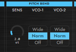
Pitch Bend Sens
Determines the maximum bend width of the Pitch Bend Wheel. The actual bend amount is determined in combination with the Bend Mode (WIDE / NORM) described below. At SENS = 100, NORM gives about ±12.5 semitones, and WIDE gives twice that, about ±25 semitones.
VCO-1 Bend Mode / VCO-2 Bend Mode
Determines whether Pitch Bend is applied to each VCO, and the width if so. Since VCO-1 and VCO-2 can be set independently, you can, for example, bend only one of them.
| Option | Meaning |
|---|---|
| WIDE | Twice the width set with the SENS knob (e.g., about ±25 semitones at SENS = 100). |
| NORM | Standard width. The actual amount is set with the SENS knob (up to about ±1 octave). |
| OFF | Pitch Bend is not applied to that VCO. |
VCO-1 / VCO-2 Bend Mode are per-section parameters.
8.9 MOD & AFTER TOUCH (AT Sens / LFO-2 Rate / Sync / LFO-2 Destination)
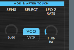
The MOD & AFTER TOUCH section controls LFO-2, which is used to add expression during performance. LFO-2 is an LFO with a fixed Triangle waveform, driven by the Mod Wheel and Channel Aftertouch.
Note
The Mod Wheel (CC1) and Channel Aftertouch share the same bus, and whichever is deeper takes priority. Whichever is acting more deeply triggers LFO-2. LFO-2 is a fixed-Triangle LFO whose amplitude rises only while you are pressing (or pressing into) the key. Its destination is set by LFO-2 Destination, its depth by AT Sens, and its speed by LFO-2 Rate.
AT Sens
The modulation amplitude (the depth of LFO-2) when the Mod Wheel or Channel Aftertouch is applied to its maximum. The two share the same bus, and whichever is deeper takes priority.
LFO-2 Rate
The frequency of LFO-2 (0.016–16 Hz, per the MKS-80 spec). The waveform is fixed at Triangle.
The small SYNC button below LFO-2 Rate switches the control between free Hz rate and host-tempo sync.
| Mode | Meaning |
|---|---|
| SYNC off | Free-running LFO-2 rate in Hz. |
| SYNC on | Host-tempo sync. The knob selects a note value from 8/1 to 1/64T, and the readout shows both the note value and the effective Hz at the current BPM. |
In tempo sync, one LFO-2 cycle equals one selected note value. If no host tempo has been received, Synth-80 uses 120 BPM as the fallback. Turning SYNC off restores the previous free Hz Rate, so you can try tempo sync without losing the original LFO-2 speed. Like LFO-1, the synced LFO-2 phase is reset on the first note from silence and when you change the note value; additional notes played while a sound is already active do not retrigger the phase.
LFO-2 Rate, SYNC, and Sync Division are per-section parameters. Upper and Lower can have different LFO-2 sync settings in DUAL / SPLIT modes; in WHOLE mode they stay synchronized like the other per-section values.
LFO-2 Destination
Selects the destination of LFO-2 (driven by the Mod Wheel / Aftertouch).
| Option | Meaning |
|---|---|
| VCO | Modulates VCO pitch (LFO-2 vibrato). |
| VCF | Modulates the VCF cutoff (a static offset; it does not pass through the LFO). |
When Destination is VCF, Rate / SYNC do not affect the sound because the MKS-80 behavior is a static aftertouch offset rather than an LFO wobble. Rate / SYNC matter when Destination is VCO.
AT Sens / LFO-2 Rate / Sync / LFO-2 Destination are all per-section parameters. You can give Upper / Lower separate vibrato settings.
8.10 Patch Volume (Per-Patch Volume Trim)
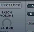
Patch Volume is a volume trim saved together with the Patch (±12 dB). Use it to even out the overall level on a per-Patch basis when volume varies from one sound to another.
Its position in the signal path is as follows.
... → Effect Chain → Patch Volume → Master Volume → output
Patch Volume sits after the Effect Chain and before the Master Volume. The difference is that, whereas Patch Volume is saved with the Patch, the Master Volume is an overall trim that is not included in the Patch. For the concepts of Master Volume, CPU load, and output level, see → Chapter 12 "Settings and Performance".
Note
When Effect Chain Lock is ON, the effect settings stay locked and are not overwritten even when you load another Patch. However, Patch Volume is not subject to the lock. For details on Effect Chain Lock, see → Chapter 9 "Effects".