
4. Screen Tour
In this chapter, we work through where everything is located on the Synth-80 screen, following along with screenshots. First we take in the whole screen at a glance, then trace each block from top to bottom, and finally re-read the layout from a different angle: the "signal flow."
This chapter only guides you to "where things are"; it does not explain the meaning of each individual knob. Detailed explanations of each parameter are gathered together: Tone (sound) is covered in → Chapter 7 "Tone Parameter Reference", performance and layer settings in → Chapter 8 "Patch / Performance Reference", and effects in → Chapter 9 "Effects".
Note
The color coding on the screen is an important cue for telling operations apart. White sections represent Tone (the Upper / Lower sound), and light-blue sections represent Patch-scope (performance / layer) parameters. This chapter, too, guides you through each block in line with this color convention.
4.1 The Whole Screen
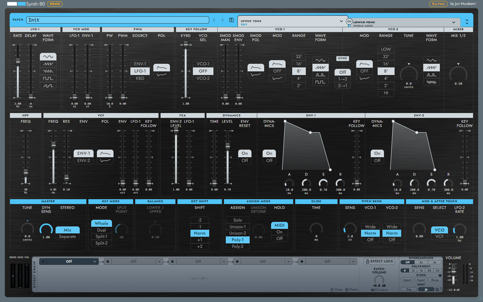
The Synth-80 screen is broadly divided into four blocks from top to bottom.
| Block | Position | Role |
|---|---|---|
| Top bar | Topmost row | Selecting, saving, and moving between Patch and Upper / Lower Tone |
| Tone editor (white) | Upper two rows | Parameters for creating each Upper / Lower sound |
| Patch row (light blue) | Below the Tone editor | Parameters related to performance and layering |
| Bottom row | The very bottom | MIDI wheels, Effect Chain, various settings, Master Volume and meter |
At the bottom right of the screen there is a resize grip; dragging it changes the size of the entire window. Saving the size and the behavior of DPI are explained in → Chapter 12 "Settings and Performance".
4.2 Top Bar (Patch / Upper Tone / Lower Tone)

The light-blue band at the very top represents the Patch you currently have open. A single Patch contains two sounds, an Upper Tone and a Lower Tone, and three blocks line up within the band: PATCH / UPPER TONE / LOWER TONE.
- Each block has the file name (sound name) currently loaded and a save button. Clicking a block opens a load menu that follows the folder hierarchy.
- The right end of the PATCH name field holds the folder badge and the forward and backward arrows. The arrows let you step through Patches in the same category (folder), forward and back. Clicking the folder name opens a load menu for that folder only.
- The Preset browser button to the right of the save button opens and closes a browser where you choose Patches while filtering by search and tags (→ 5.7). After you load a Patch from filtered results in the browser, the badge changes to a filter mark with the name of the filter, and the arrows cycle through those results.
- The forward and backward arrows of UPPER TONE / LOWER TONE replace the Tone one step at a time through the Tones in the library, in the same order as the load menu.
- The link icon between UPPER TONE and LOWER TONE appears when both paths match, and toggles whether sound editing is linked across Upper / Lower.
- The collapse / expand button at the far end switches the Tone editor between single-section display (collapsed) and simultaneous two-row top-and-bottom display (expanded) (see → 4.6). When expanded, you can edit Upper and Lower at the same time.
Note
For the Patch name, the file name is the source of truth. The unit of saving is the Patch (extension .80p). The concepts of Patch / Tone are explained in detail in → Chapter 5 "Understanding Preset / Patch / Tone".
4.3 Tone editor (White = Sound)
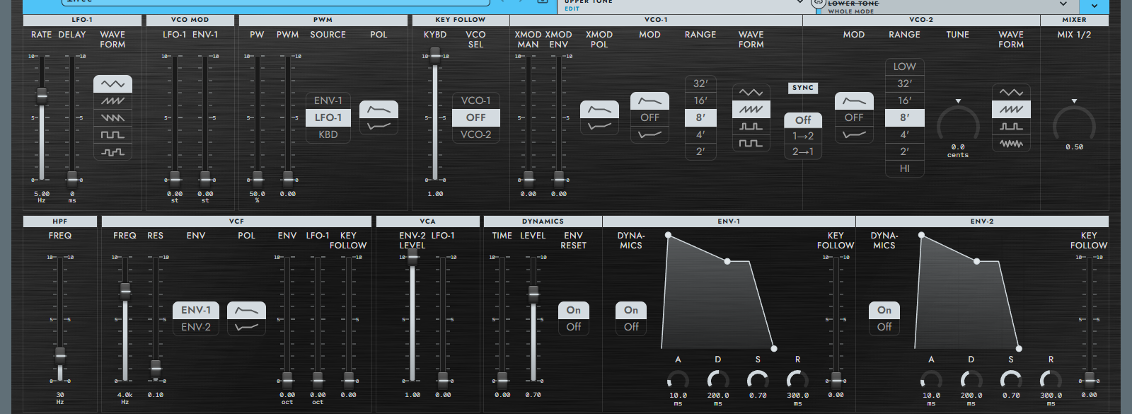
The group of white sections in the upper half of the screen is the Tone editor. This is where you create each Upper / Lower sound.
First row (left to right)
| Section | Main contents |
|---|---|
| LFO-1 | The main LFO for adding vibrato (waveform, free / tempo-synced rate, delay) |
| VCO MOD | Pitch modulation of the VCO by LFO-1 / ENV-1 |
| PWM | Pulse width modulation |
| KEY FOLLOW | Tracking of VCO / VCF / ENV according to keyboard pitch |
| VCO-1 | The first oscillator (waveform, range) |
| VCO-2 | The second oscillator (waveform, range, tune, Sync / Cross Mod) |
| MIXER | The balance of VCO-1 / VCO-2 / Noise |
Second row (left to right)
| Section | Main contents |
|---|---|
| HPF | High-pass filter (tidying up the low end) |
| VCF | Low-pass filter (brightness, resonance) |
| VCA | The volume stage |
| DYNAMICS | Response to Velocity / Aftertouch |
| ENV-1 | The envelope for the VCF / VCO system |
| ENV-2 | The envelope for the VCA system |
Note
Whether you are editing Upper or Lower can be told from the color of the section band and from the knob highlight color (accent). Switching the UPPER TONE / LOWER TONE tabs in the top bar switches the target shown across the entire Tone editor. For the meaning of each section's parameters, refer to → Chapter 7 "Tone Parameter Reference".
4.4 Patch Row (Light Blue = Performance / Layer)

The group of light-blue sections below the Tone editor is the Patch row. These are not the sound itself but parameters that determine how you perform and how layers are built.
| Section | Main contents |
|---|---|
| MASTER | Master Tune, Dynamics Sens, Stereo Mode |
| KEY MODE | Selecting Whole / Split / Dual, and the Split Point |
| BALANCE | The volume balance of Upper / Lower |
| OCT SHIFT | Octave shift |
| ASSIGN MODE | Voice assignment (Solo / Unison / Poly), Unison Detune, Hold |
| GLIDE | Portamento time |
| PITCH BEND | Bend range, the bend mode of VCO-1 / VCO-2 |
| MOD & AFTER TOUCH | Aftertouch sensitivity, the destination and free / tempo-synced rate of LFO-2 |
Note
MASTER / KEY MODE / BALANCE are settings shared across the whole Patch. The five sections from OCT SHIFT onward, on the other hand, are "per-layer" parameters that can hold separate values for Upper / Lower in DUAL. For details of each parameter, refer to → Chapter 8 "Patch / Performance Reference".
4.5 Bottom Row (Wheels / Effects / Settings / Master)

At the very bottom of the screen, the things that move during performance and the settings you do not usually touch are gathered together. They are arranged from left to right.
- MIDI wheels (BEND / MOD / VOL): Display the current values of Pitch Bend, Mod Wheel, and Volume coming in from an external keyboard. BEND returns to center when you release the mouse.
- Effect Chain (the LCD-style panel in the center): An effect chain that connects 5 slots in series from left to right. You select each slot with a tab, and can rearrange the order by dragging. For details, refer to → Chapter 9 "Effects".
- Settings (the right end of the LCD panel): OVERSAMPLING and POLYPHONY switching, SysEx (select a MIDI port from the MIDI icon), and Hint (the display language for hints) are lined up. For the meaning of the settings, refer to → Chapter 12 "Settings and Performance", and for SysEx to → Chapter 11 "SysEx / MKS-80 Integration".
- Master Volume and meter (far right): The volume of the final signal stage and the level meter. This is an overall volume trim that is not saved to the Patch.
Note
The bottom row has two volumes with similar names: "Patch Volume" and "Master Volume". Patch Volume is after the Effect Chain and before Master Volume, and is a volume that is saved to the Patch. Master Volume is an overall trim that is not included in the Patch. The difference is explained in → Chapter 12 "Settings and Performance".
4.6 Collapsing and Expanding (collapsed / expanded)
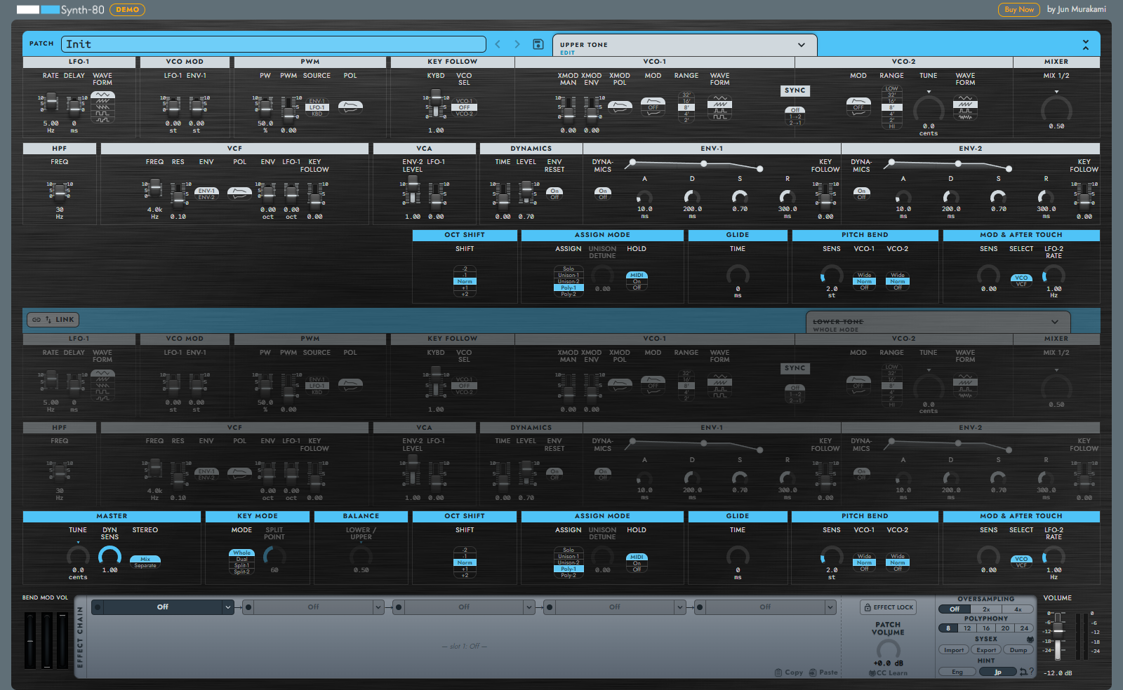
The Tone editor has two display modes.
| Mode | Display | Use |
|---|---|---|
| collapsed | Shows only one of Upper / Lower at a time | Normally this one. Switch the editing target with the tabs |
| expanded | Shows Upper / Lower simultaneously in two rows, top and bottom | When creating while comparing two sounds in DUAL / SPLIT |
You switch with the collapse / expand button in the top bar. When you expand, the window grows vertically, and the Upper block and the Lower block are each shown independently.
4.7 Dimmed Display of Parameters That Have No Effect
Parameters that have no effect on the sound in the current Key Mode or editing target are automatically shown dimmed. For example, in WHOLE mode the Lower Tone does not sound, so the Lower-side sections are shown dimmed. The Split Point is dimmed outside of SPLIT, and Unison Detune is dimmed outside of Unison.
Even when shown dimmed, the controls themselves can still be operated, and the set values are saved. If you switch to a mode where they take effect, those values are used as they are. The dimming is simply a marker that says "this is not affecting the sound right now."
Note
If you feel that "I set it but the sound doesn't change," first check whether that parameter is dimmed. Depending on the state of Key Mode or Assign Mode, it may be intentionally disabled.
4.8 Signal Flow Overlay (Displaying Connection Lines)
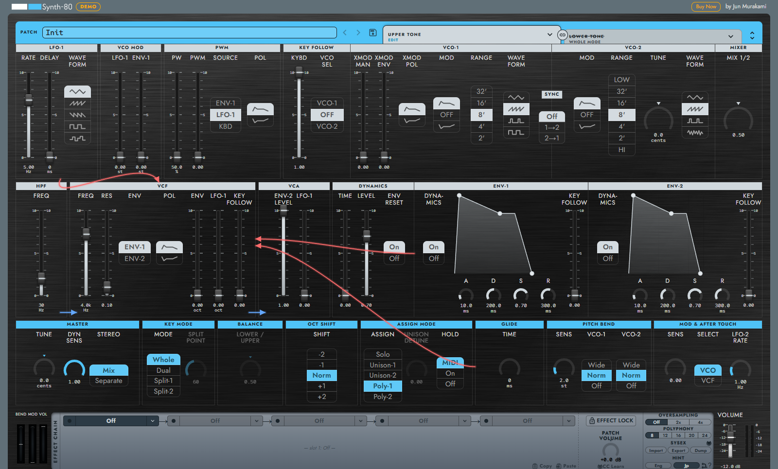
So far we have guided you through each block by its "location on the screen," but Synth-80 also has a feature for visually confirming "how the signal flows." That is the signal flow overlay.
When turned on, hovering the mouse over any module draws lines showing the connections related to that module. There are two kinds of lines, audio (blue) and modulation (red), and arrows show the direction. For example, if you hover over LFO-1, you can see at a glance which destinations LFO-1 is sending modulation to.
You toggle this overlay on / off with the small branching-arrow toggle button at the lower right of the HINT settings button. The setting is saved and carried over to the next startup.
Note
The signal flow overlay helps those who are not yet accustomed to the signal path of a subtractive synth grasp "which knob now affects what." The way of thinking about sound design itself is explained along the signal path in → Chapter 6 "Sound Design Basics".